Replacing the electrolytic triple capacitor

The Gibson Recording Amp seems to have originally had radial capacitor that was a triple capacitor, having the vaues of 22/20/20 UF and rated at 450 volts.   In investigating the possible causes of the low frequency wall-rattling rumble it seemed more and more likely that all or part of this triple-capacitor was not functioning properly and was letting higher frequencies through to the amplifier.   This was a rumble that you knew to shut down the amp immediatly because it would grow quickly and threaten to blow out the speakers.

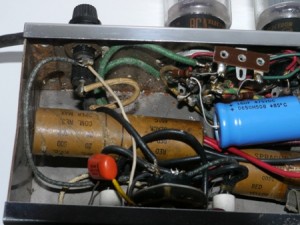
I had questions about replacing it becasue I could not find any source of electrolytic capacitors like this.   You can see this capacitor below, which looks like a paper coin wrapper.   I you look closely you can the tube has been distorted by the spring steel clamp that holds it.

Triple Capacitor

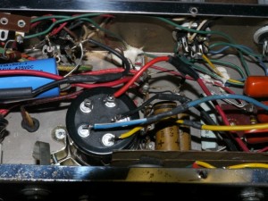
I searched quite a bit, but I could not find a source for capacitors like this old radial electrolytic, which was apparantly a triple-capacitor.   The best solution I could come up with was to replace it with a can type capacitor that was a three or four in one.   I cut out the old cap.   I wanted to remove the rivit which attache the cap holder but it was backed by the choke.   The two nuts that held the choke in place were difficult to reach and spun when I tried to remove the bolts from the outside of the case.   I fnally found a way to hold them from spinning and got them free but it was tedious.    I used a new rivit to install a holder for new capacitor and there was just barely enough room to squeze it in amon the existing wiring.

I had to extend the wiring to allow it to reach to the new cap.  Here is a picture of how it looks installed:

Can Capicitor

Not shown here is that I used rivits to secure the choke back to the amplifier case.   This was much easier than trying to fit in the old bolts and also felt like a more sturdy installation.  If I have to remove the choke again it will be easy to drill out the rivits from the outside of the case.

Values:  The values of the old triple capacitor was 22/20/20 uf  450 Volts.   The new capacitor is a quad and is rated at 40/20/20/20  500 Volts.     I opted to try the 40 to replace the 22 uf.  Its’ my understanding that this may increase the bass and it’s better to go to a higher than a lower value than before.    If I’m not happy with the sound I may switch it to a 20 uf post (so I have an option either way).

I must say, it was very satisfying to start up the amp and to find that the low rumble in 2nd and 3rd  “ON” positions was completely gone.


Tube Amp Blown Capacitor Repair

DISCLAIMER – The repairs mentioned on this site are from personal experiences.   Please do not take any information here and think you’re equipped to work on your amp.   I’m told there are some things in there that can retain enough voltage to kill or seriously hurt you.   I take my own chances….you take yours.


Filter Capacitor

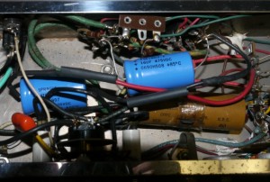
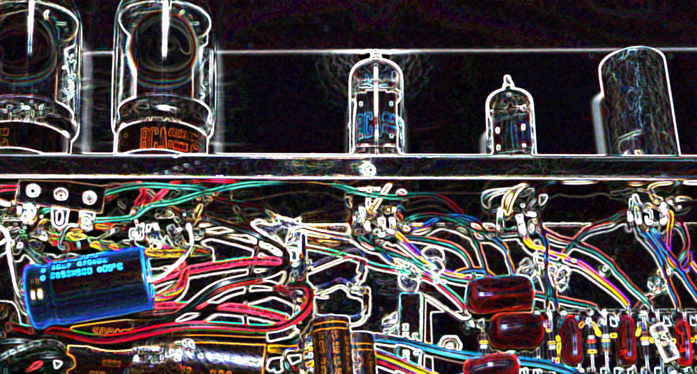
The round paper tubes that look like a roll of pennies are the old electrolytic capacitors.   The crud yousee in the upper left of the case looks like where the liquid contents of a blown or previously blown capacitor sprayed the inside of the amp.  It looked at first as if it was all rust but some of it rubbed right off.   Avoid touching the capacitors….take great care because they can store a charge well after the amplifier is turned off and unplugged.    I probed them for DC current and they had been discharged.    The blue capacitor to the right was a modern replacement for the one that was obviously blown.   I found of  the same value, and soldered it in.   Turns out the other large capacitor you see in the photo below was also blown.   This one had leads coming out one side and looked like  a firecracker with fuses.   I had trouble finding one with the same electronic value and the same design so I settled with one of a similar value and added a length of wire in order to connect to the same locations.   Also notice the old wiring coming in from the fuse….this was an 2 prong ungrounded chord and in a later post I’ve also decided to upgrade that to 3-prong.


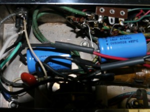
New Caps

In the photo above you can see both new capacitors in place.  The new capacitor is smaller in length but is a little stubby compared to the one it replaced.   You can see the wire snaked over from the left side and covered with some heatsrhink tubing.    You may also spot the new power chord with the green grounded wire.    I plugged the amp in and for the first time in a long time it did not immediately blow the main fuse.   The Standby circuit seemed to work fine and it’s pilot light was glowing instead of flickering.   That seemed like progress.   Once the tubes seemed warm I moved the switch to “ON” and amost immediately I got a terrible low frequency rumble that threatened to blow out the speakers.   It seemed unaffected by the volume controls…so I shut down the amp immediately.    Experimenting a bit…I was able to get the amp to play while the tubes reahced operating temperature.   This still felt like progress because at least I was not blowing the fuse and I was getting a nice sound…but as soon as the tubes warmed up….Deep Rumble again!!      While fiddling around with plugging the guitar in one of the four inputs I also discovered that there was a short in one.    That will be mentioned in a future post.